This means that two of the three conductors are dedicated to carrying the ‘hot’ and ‘cold’ path for the circuit carrying the signal, and the third conductor connects the ground of each component. The electrical circuit used to pass a signal between sound equipment is ‘balanced’. The cables used to connect components of a sound system have three wires (conductors), similar to the three prong plug used to supply power to grounded electrical equipment. The phase inversion switch (Ø) reverses the polarity of the transformer’s output to the sound system (more on this in the acoustics section). A ground lift allows the sound system’s common ground (shared by all the components in the sound system) to be isolated from the source signal’s ground. A pad is basically a heavy-duty volume control to permit the input of amplified sources. Most DI boxes have a “thru” output that allows an instrument’s sig nal to continue (unaffected) to an amplifier after passing through the transformer’s windings. DI boxes are available with a number of features that can include: a ‘pad’, ground lift, and phase inversion. The instrument’s signal passes through a wire which induces a similar current in another wire that is wound (many times) around it.

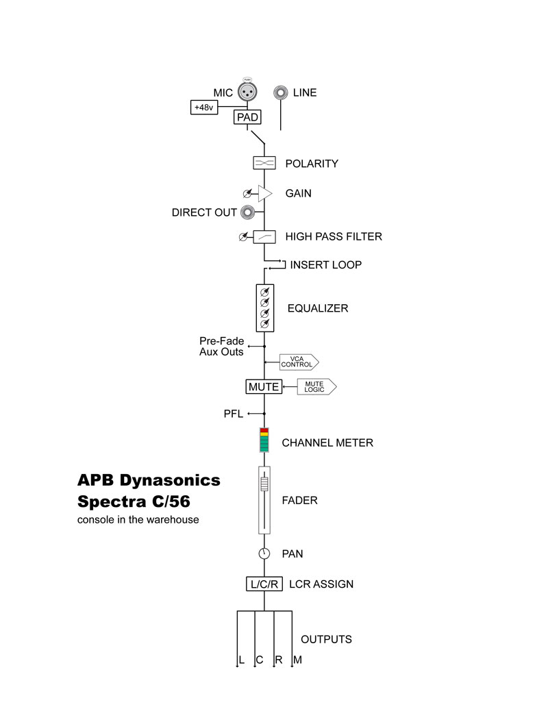
- Microphones are generally selected to complement the qualities of the sound source that they will be used to detect (more on this in the section about microphones and loudspeakers).The characteristics and features of these devices vary widely between different manufacturers and models. These devices convert the sound or the electrical signal from an instrument or voice into an electrical signal that is compatible with the components of a sound system. It will light up every time a trigger impulse is being received.Signal flow diagram illustrating the path that a signal follows in a typical PA system.Īn input device is the interface between a sound source and the sound system. In most cases, it will consist of either a microphone or a direct input (DI) box. The LED to the left of envelope 1 will indicate when an external audio signal passes the threshold. The audio input also features a gate-trigger detector so that the envelopes and LFO 1 in reset mode will be triggered when an incoming audio signal reaches a threshold determined by the input gain level. If you don’t adjust the input gain manually, the gain defaults to a line input level that makes an external audio signal as loud as the Super 6’s oscillator signals. Return to editing your sound by pressing the SHIFT button again.Turn the MIX rotary control in the mixer section to adjust the input gain.
Signal path audio Patch#
Press the SHIFT button to the right of the patch and bank select buttons.You can also adjust the input gain of an external audio signal:

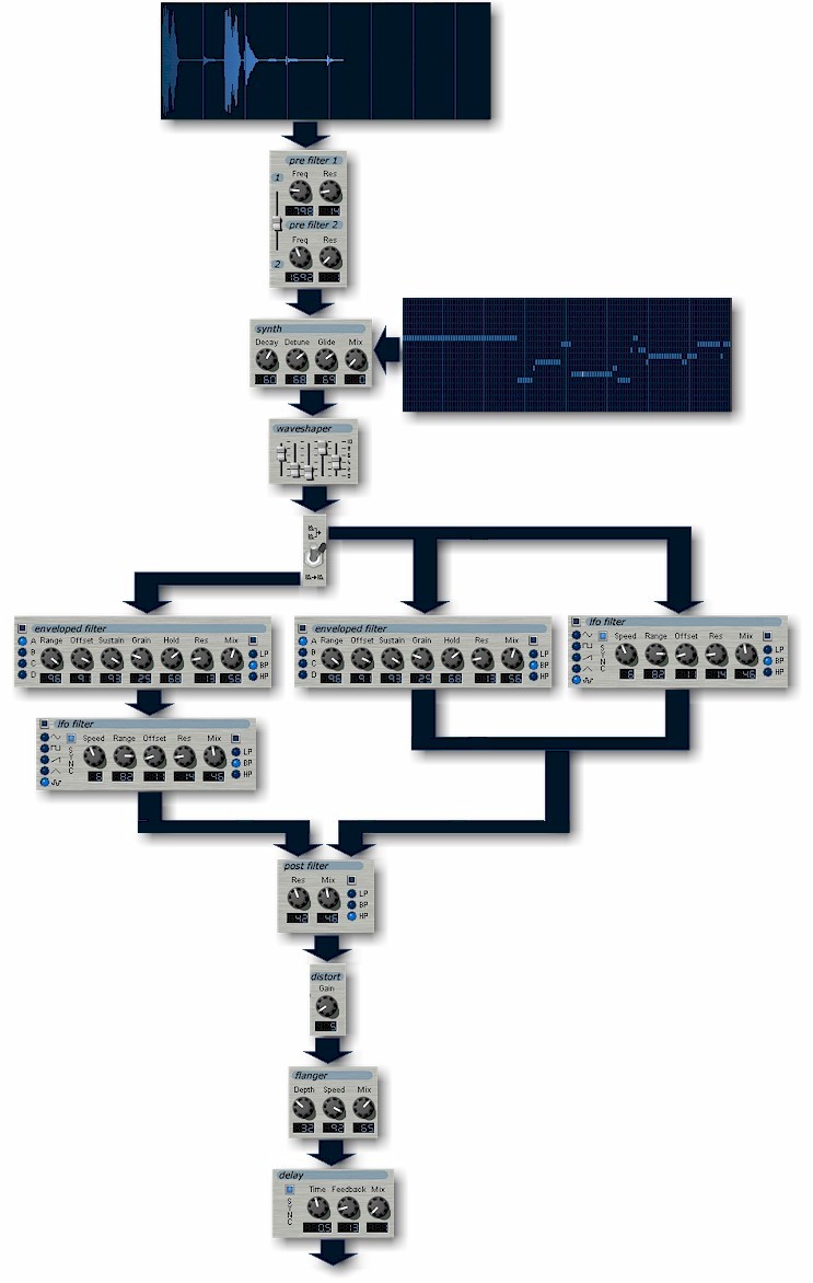
After the mixer, the external audio signal is routed through the voltage controlled filter (VCF), the voltage controlled amplifier (VCA) and the effects section all of which allow you to further modify and process the incoming signal. Here, the external audio signal simply replaces that of DDS 2. You can control the balance between the audio signals of DDS 1 and an external audio source with the MIX rotary control in the mixer section. In this mode the audio signal of DDS 2 is bypassed to give way to an external audio signal, which is routed via the DDS 2 channel into the mixer. Note: When you feed an audio signal into the signal path of the Super 6, it will trigger a gate signal as soon as it passes a certain threshold level, unless you select POLY 2 in the voice assign section.Īs you may have noticed these settings activate DDS 2’s LFO mode. If LFO 1 is in HF TRK mode and the mode toggle switch is set to DDSĢ, LFO 1’s signal will be mixed in with the external audio signal your Super 6 is receiving through DDS 2’s audio channel.

Flip the toggle switch to the upper position next to which it says AUDIO.Turn the RANGE rotary control to the leftmost position marked LFO.Turn the MIX rotary control fully clockwise so that only the audio signal of DDS 2 can be heard. Press down a key or engage the hold mode.Connect an external audio source to the audio input on the rear side of the Super 6 by using a stereo 1/4 inch jack.You may also use the DDS 2 module to process an external audio signal:


 0 kommentar(er)
